Sheet metal starts on a laser; structural steel starts on a saw. Wide-flange beams, channels, angles and tube arrive in stock lengths and leave as finished members — cut to length, drilled, coped, notched and marked — ready to fit up, weld, galvanize and bolt together in the field. Substation structures, transmission steel, equipment platforms, pipe racks and support steel for generation plants and data centers all go through this sequence. Here is what each machine does and why it matters to the finished structure.
Need parts cut, formed, welded or finished? Call 601.892.5017 or email collin.t@fabtekindustries.com — send the drawing and we’ll quote it.
- Structural processing turns stock-length shapes into finished members in four operations: saw to length, make holes (drill, punch or plasma), cope and notch the ends, and mark the piece — all before fit-up and welding.
- CNC beam lines run directly from the detailing model (Tekla or SDS/2, exported as DSTV/NC1 files), so hole location is held to about ±1/16″ and every member carries its piece mark.
- Robotic plasma copers handle copes, notches, bevels and slots; drill lines handle high hole counts; angle lines punch and shear bracing. Most support structures use all three.
- Laser vs. Plasma vs. Waterjet Cutting
- Fiber Laser Cutting: Thickness, Tolerance & Edge Quality
- Structural Steel Processing: Coping, Drilling & Sawing (you are here)
- Press Brake vs. Panel Bender
- Plate Rolling: Cylinders, Cones & Tank Shells
- When a Fabricated Part Needs Machining
- MIG vs. TIG vs. Laser Welding
- How Powder Coating Works
- Abrasive Blasting & SSPC Surface Prep
The four operations
Sawing. CNC band saws cut members to length, straight or mitered, from stock lengths of 20 to 60 feet. On heavy shapes this is still the most accurate way to get a square end. Hole-making. Bolt holes for splices, connections, bracing and equipment mounting are drilled, punched or plasma-cut, depending on thickness and specification. Coping and cutting. The ends of members are shaped so they fit their neighbors: flange copes so a beam frames into another beam, notches, slots, weld-prep bevels and cutouts. Marking. Piece marks, layout lines for attachments and weld locations are scribed or etched on the member so the fitter and erector don’t measure by hand.
Before CNC lines, each of these was manual: a layout man with a tape and soapstone, a radial-arm or magnetic drill, and a hand torch for copes. Every hole was a chance for error, and a mislocated hole was found in the field, on a galvanized member, where it is most expensive to fix.
From model to machine
A modern structural job is detailed in a 3D model — Tekla Structures, SDS/2 or similar — and each member is exported as a DSTV (NC1) file: profile, length, end cuts, every hole with its diameter and location, copes and marking. The beam line reads that file directly. No one re-types a dimension, so the only way a hole lands in the wrong place is a model error or a revision that reached one member and not its mate — which is why change control on the model matters as much as the machine (see Substation Change Orders). Working from the model, a CNC line routinely holds individual hole location to about ±1/16″ and hole groups to the drawing, the tolerances in our bolt-hole spec sheet.
Coping, notching and bevels
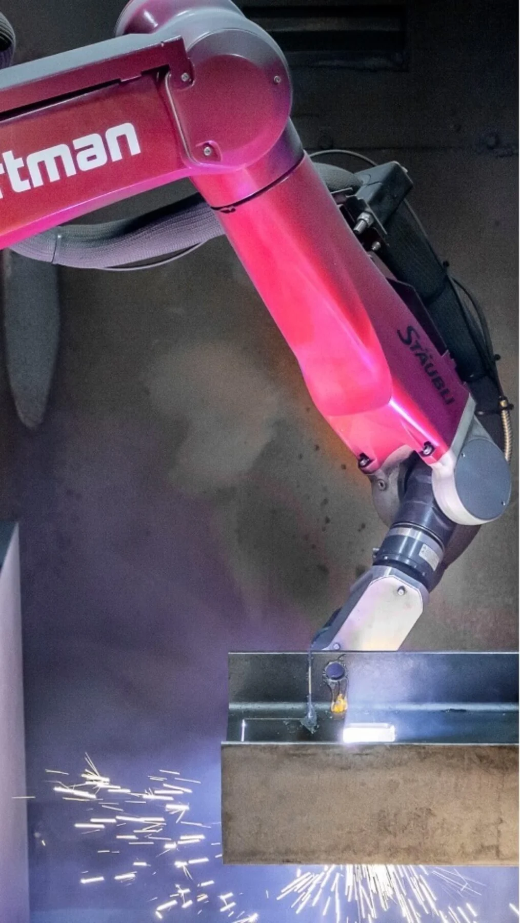
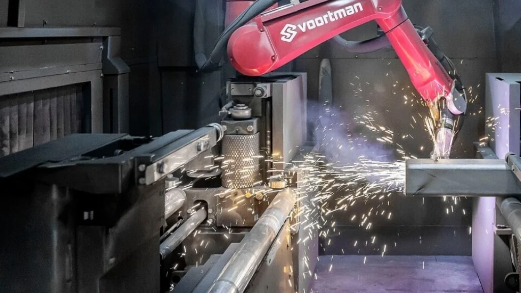
A cope removes part of a beam’s flange and web so it can frame into another member at the same elevation; a notch or block cut clears a connection; a bevel prepares a full-penetration weld joint. Done by hand, a cope takes layout, a torch and grinding, and the radius at the corner of the cope — which matters for fatigue and for the code — depends on the operator. A robotic plasma coper cuts the full profile in one pass under CNC control, with a consistent corner radius, and can cut bolt holes, slots, bevels and marking in the same setup. Seven-axis robots reach all faces of wide-flange, channel, angle, flat bar, HSS and pipe without re-fixturing.
Drilled, punched or plasma holes
| Method | Hole quality | Where it fits |
|---|---|---|
| CNC drilling | Round, straight, smooth bore; no hardened edge | Beams and channels with many holes; thick flanges; specs requiring drilled holes |
| Punching | Fast; slight taper and a sheared zone | Angle and flat bar bracing, within the thickness limits of the code |
| Plasma-cut holes | Good on modern HD plasma; thin heat-affected ring | Slots, large holes and copes; small bolt holes only where the spec allows |
| Sub-punch or sub-drill and ream | Best fit-up accuracy | Critical connections and thick material |
AISC permits punched holes only in material within set thickness limits (roughly the bolt diameter plus 1/8″ for mild steel), and current editions allow thermally cut holes within surface-roughness limits. Many utility and owner specifications are stricter and require drilled holes — check the project specification.
Where structural processing is used
Anything built from shapes rather than sheet: substation structures such as dead-ends, A-frames, bus supports and switch stands; transmission structures; equipment skids, platforms and mezzanines; stair towers and crossovers; pipe and cable racks; gantries; and support steel for generation facilities, BESS yards and data centers. The same machines also process the base channels and frames of large enclosures and tank bases.
Marking and match-marking
A structure ships as hundreds of members, and the erector has to find each one. The beam line scribes or etches the piece mark from the erection drawings on every member, and layout marks for clips, stiffeners and attachments, so fit-up in the shop is faster and the member is still identifiable after galvanizing. Heat numbers from the mill test report follow each member as well (see Material Certs & Heat Numbers). Match-marking and delivery sequencing are covered in Substation Steel Delivery.
How FabTek runs it
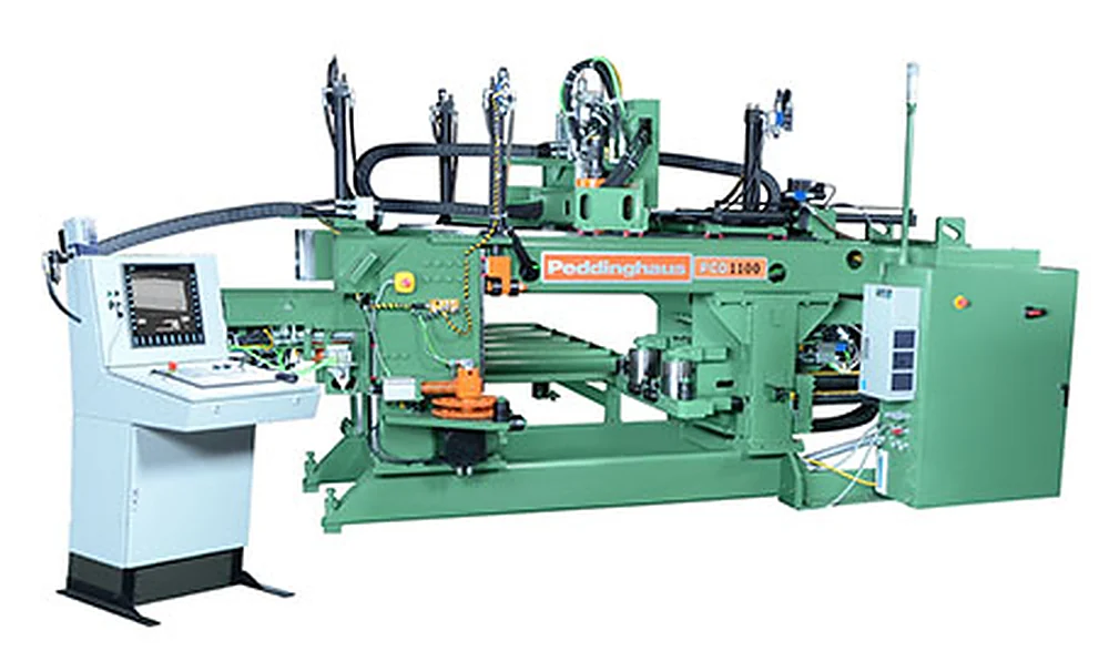
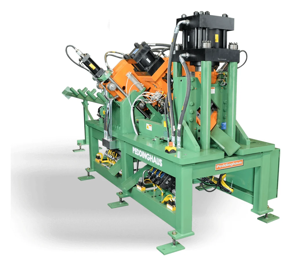
FabTek’s structural cell starts with an HE&M DC-2038RB1 band saw (36″ capacity) and supporting saws, then a Peddinghaus PCD-1100B three-spindle drill line that drills three faces in one pass, two Voortman V807 seven-axis robotic plasma copers for copes, notches, bevels, slots and marking, and a Peddinghaus Anglemaster 643 angle line and Geka Hydracrop 110/A ironworker for bracing and flat bar. Programs come straight from the structural model — Tekla, SDS/2, IFC, DSTV/NC1 — with FabTek’s engineering group detailing to the structures package when the customer supplies design drawings. Members go on to fit-up, AWS D1.1 welding and hot-dip galvanizing through FabTek’s long-standing partners, with heat numbers and piece marks carried the whole way.
Frequently asked questions
What is beam coping?
Coping is cutting away part of a beam's flange and web at the end so it can frame into another member at the same elevation. It is done by hand with a torch or, on modern lines, by a CNC or robotic plasma coper that cuts the profile, holes and bevels in one pass from the detailing model.
What is a DSTV or NC1 file?
DSTV, often called NC1, is the standard file format structural detailing software such as Tekla and SDS/2 exports for CNC steel processing. Each file describes one member: profile, length, end cuts, holes, copes and marking, so the beam line runs without anyone re-typing dimensions.
Can bolt holes in structural steel be punched or plasma cut?
Sometimes. AISC allows punched holes within thickness limits and, in current editions, thermally cut holes within surface-roughness limits. Many utility and owner specifications require drilled holes, so the project specification governs.
What tolerance does a CNC drill line hold?
Working from the detailing model, a CNC drill line routinely holds individual hole location to about plus or minus 1/16 inch and hole groups to the drawing, consistent with the AISC Code of Standard Practice and typical utility specifications.