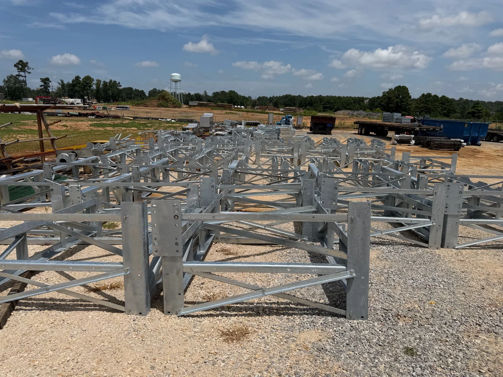
A substation structure that does not bolt up is almost always a hole problem — wrong size, wrong place, or a base plate that leaves no room for the foundation contractor’s tolerance. Here are the hole sizes and tolerances that govern substation steel, and how they are held in fabrication.
Need this built to your spec? Call 601.892.5017 or email collin.t@fabtekindustries.com — send the drawing and we’ll quote it.
- Standard holes for structural bolts are bolt diameter + 1/16″ through 7/8″ bolts and + 1/8″ for 1″ and larger (AISC). Oversized and slotted holes have defined dimensions and require the engineer’s permission.
- Anchor-bolt holes in base plates are much larger — per AISC Design Guide 1, e.g. 1-5/16″ for a 3/4″ anchor and 1-13/16″ for a 1″ anchor — with plate washers, to absorb foundation setting tolerance.
- Fabrication holds hole location to about ±1/16″ and group-to-group to the drawing; a robotic beam line places holes from the model so that tolerance is routine.
- What Gauge Steel for a NEMA 3R Walk-In Enclosure?
- ASTM A123 vs. A153: Which Galvanizing Spec Applies?
- Minimum Bend Radius for 5052 Aluminum Sheet
- Powder Coat Film Thickness for Outdoor Electrical Enclosures
- IEEE 2000-Hour Salt Spray: What the Rating Actually Means
- AWS D1.1 vs. D1.3 vs. D1.6: Which Welding Code Applies?
- Bolt-Hole Tolerances for Substation Steel Structures (you are here)
- Non-Segregated Bus Duct: Ampacity, Bar Size and Housing
- Material Certs and Heat Numbers: What Traceability Means
- How to Spec Anchor-Bolt Patterns for Equipment Stands
The answer
For steel-to-steel connections on substation structures — splices, cross-arm to column, brace to gusset — holes follow the AISC Specification for Structural Steel Buildings (Table J3.3): a standard hole is the bolt diameter plus 1/16″ for bolts through 7/8″, and plus 1/8″ for 1″ and larger. Oversized and slotted holes are permitted only where the design allows them and with the bolting conditions the code requires. For anchor bolts through base plates, holes are deliberately oversized per AISC Design Guide 1 and fitted with plate washers, because anchor bolts set in concrete cannot be placed as precisely as holes drilled in steel. For equipment-stand top plates, hole size and pattern follow the equipment manufacturer’s mounting drawing exactly. FabTek drills all three on a Voortman robotic beam line and laser or plasma table, from the model.
Structural connection hole sizes (AISC Table J3.3)
| Bolt dia. | Standard · Oversized · Short slot (W × L) · Long slot (W × L) |
|---|---|
| 5/8″ | 11/16 · 13/16 · 11/16 × 7/8 · 11/16 × 1-9/16 |
| 3/4″ | 13/16 · 15/16 · 13/16 × 1 · 13/16 × 1-7/8 |
| 7/8″ | 15/16 · 1-1/16 · 15/16 × 1-1/8 · 15/16 × 2-3/16 |
| 1″ | 1-1/8 · 1-1/4 · 1-1/8 × 1-5/16 · 1-1/8 × 2-1/2 |
| ≥ 1-1/8″ | d + 1/8 · d + 5/16 · (d + 1/8) × (d + 3/8) · (d + 1/8) × 2.5d |
Dimensions in inches per the current AISC Specification; oversized and slotted holes carry restrictions on slip-critical connections and load direction — the engineer of record decides where they are allowed.
Anchor-bolt holes in base plates
AISC Design Guide 1, Base Plate and Anchor Rod Design, recommends oversized holes in column and structure base plates so the steel can be set over anchors that were placed to concrete tolerances, with heavy plate washers welded or placed to transfer load:
| Anchor rod dia. | Base-plate hole · Plate washer (min.) |
|---|---|
| 3/4″ | 1-5/16″ · 2″ × 2″ × 1/4″ |
| 7/8″ | 1-9/16″ · 2-1/2″ × 2-1/2″ × 5/16″ |
| 1″ | 1-13/16″ · 3″ × 3″ × 3/8″ |
| 1-1/4″ | 2-1/16″ · 3″ × 3″ × 1/2″ |
| 1-1/2″ | 2-5/16″ · 3-1/2″ × 3-1/2″ × 1/2″ |
Per AISC Design Guide 1 recommendations; the engineer of record may specify otherwise. Anchor rods are typically ASTM F1554 Gr. 36, 55 or 105.
The reason this matters on a substation: anchor bolts are set by the foundation contractor to ACI 117 tolerances — roughly ±1/4″ in plan for smaller bolts and more for larger — and the base plate has to fit over them without field reaming galvanized steel. See anchor-bolt pattern specs for the foundation side.
Location tolerances
The AISC Code of Standard Practice and typical utility specifications hold individual hole location to about ±1/16″ from the detailed dimension, hole groups to the drawing position within a similar tolerance, and member length and camber within its own limits. A robotic beam line cuts, drills and marks from the shop-drawing model and holds these tolerances as a matter of course; the risk of a mismatched splice comes from a drawing error or a revision that reached one member and not its mate, not from the drilling. ASCE 113, the substation structure design guide, references these fabrication tolerances and adds structure-level erection tolerances for plumb and elevation that the erector holds with shims and leveling nuts.
Equipment-stand top plates
A breaker, switch or arrester stand is drilled to the OEM’s approved mounting drawing: hole diameter as the OEM specifies (often standard-hole clearance over the equipment’s mounting bolts), pattern to the OEM’s dimensions, and orientation marked so the stand is set with terminals facing the right way. The stand is not released for fabrication until that drawing is in hand — the discipline we describe in The Structures Package. Where equipment is not yet awarded, the engineer may specify a pattern accommodating two approved manufacturers, or a top plate to be drilled later as a separate release.
How to write it
“Bolt holes for structural connections shall be standard holes per AISC Specification Table J3.3 unless oversized or slotted holes are shown on the design drawings. Anchor-rod holes in base plates shall be sized per AISC Design Guide 1 with plate washers as shown. Equipment-stand mounting holes shall match the equipment manufacturer’s approved mounting drawing, referenced by number and revision. Hole location tolerance ±1/16″. No field reaming or drilling of galvanized steel without the engineer’s approval; repair per ASTM A780.”
How FabTek handles it: Members are processed on a Voortman V807 robotic beam line and plates on laser or plasma with holes placed from the shop-drawing model; base plates are oversized per AISC DG1 unless the design says otherwise; stand top plates are drilled to the OEM mounting drawing by number and revision; and bolt patterns are checked before galvanizing. If your drawing calls for something different, send it — we build to print. Request a quote.
Frequently asked questions
What size hole for a 3/4 inch structural bolt?
A standard hole is 13/16 in. — bolt diameter plus 1/16 in. — per AISC Specification Table J3.3. Oversized is 15/16 in., a short slot 13/16 × 1 in., and a long slot 13/16 × 1-7/8 in., where the engineer permits them.
How big should anchor bolt holes in a base plate be?
Larger than structural holes, to absorb concrete placement tolerance: AISC Design Guide 1 recommends 1-5/16 in. for a 3/4 in. anchor rod, 1-13/16 in. for 1 in., and 2-5/16 in. for 1-1/2 in., each with a heavy plate washer.
What is the hole location tolerance for fabricated steel?
Typically ±1/16 in. from the detailed dimension for individual holes, with hole groups held to the drawing position within a similar tolerance, per the AISC Code of Standard Practice and common utility specifications. Robotic beam lines hold this routinely.