Once a flat blank is cut, most sheet-metal parts are formed — bent into the boxes, channels, doors, flanges and housings that become cabinets, enclosures and brackets. Two machines do nearly all of it: the CNC press brake and the automated panel bender. They bend metal in completely different ways, and the difference shows up in what parts they suit, what the part looks like and what it costs. Here is how each works and the rules that govern bend design on both.
Need parts cut, formed, welded or finished? Call 601.892.5017 or email collin.t@fabtekindustries.com — send the drawing and we’ll quote it.
- Press brake: a punch pushes the sheet into a V-die. It is flexible, handles thin sheet to heavy plate and complex short parts, and the operator handles the part between bends.
- Panel bender: the sheet is clamped flat and a blade swings up or down to fold each flange. Best for long, wide panels — cabinet skins, doors, roofs — with many flanges and hems, and it leaves no die marks on the show face.
- In air bending, the inside radius comes out about 15–16% of the die opening, and the die opening is usually 6–10 times material thickness — which in turn sets the minimum flange length.
- Laser vs. Plasma vs. Waterjet Cutting
- Fiber Laser Cutting: Thickness, Tolerance & Edge Quality
- Structural Steel Processing: Coping, Drilling & Sawing
- Press Brake vs. Panel Bender (you are here)
- Plate Rolling: Cylinders, Cones & Tank Shells
- When a Fabricated Part Needs Machining
- MIG vs. TIG vs. Laser Welding
- How Powder Coating Works
- Abrasive Blasting & SSPC Surface Prep
How a press brake bends
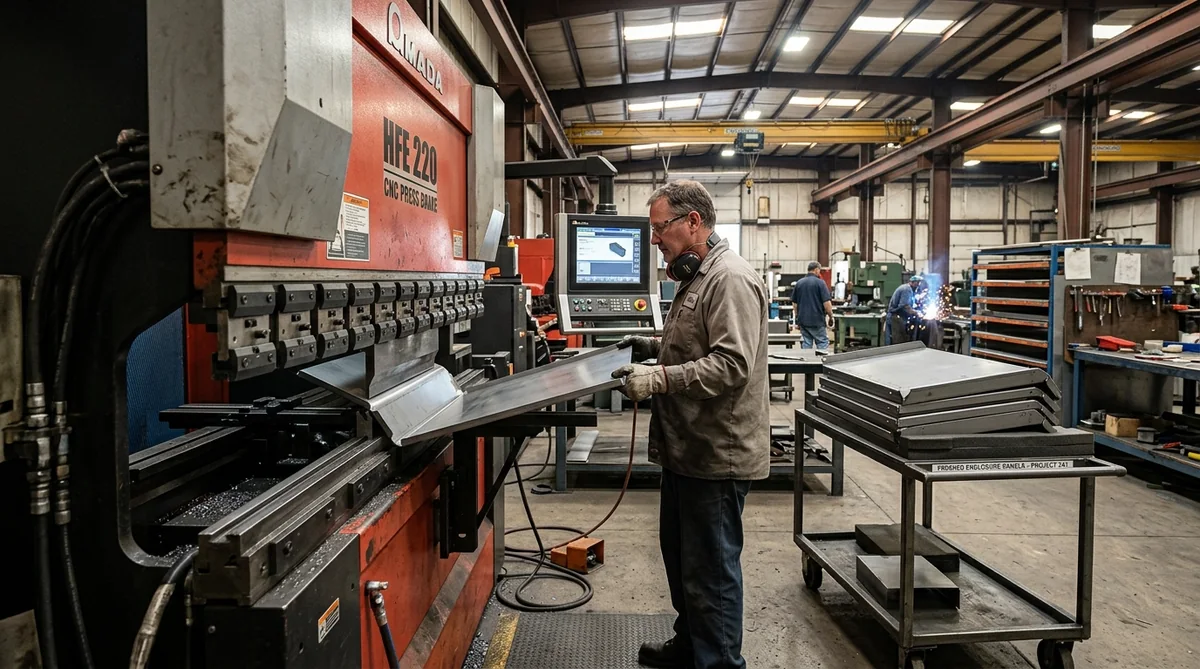
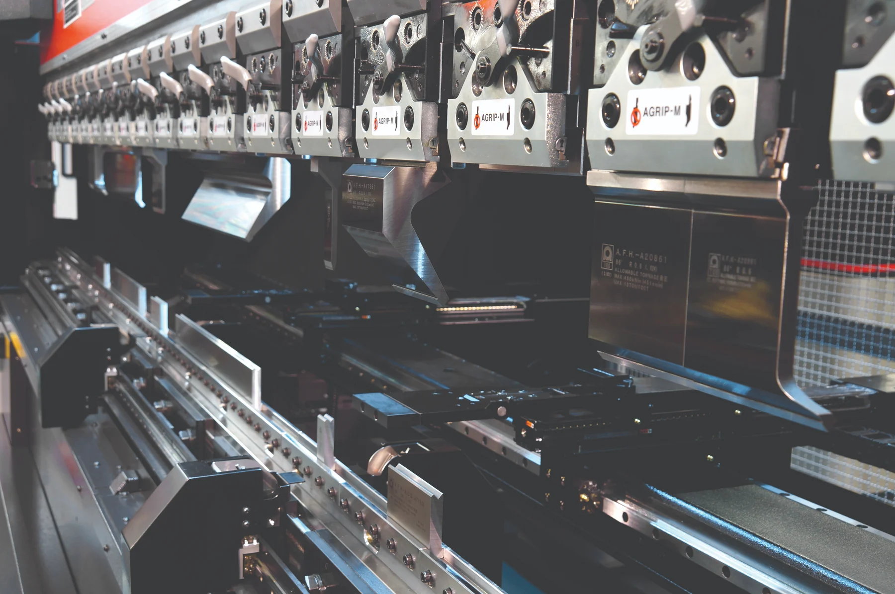
A press brake is a long, narrow press. A punch on the moving ram presses the sheet into a V-shaped die on the bed, and the depth the punch travels sets the bend angle. Most modern work is air bending: the sheet touches only the punch tip and the two die shoulders, so one set of tooling can make many angles simply by changing ram depth. Bottoming and coining press the sheet fully into the die for tighter angle control at much higher force, and are now used mostly for special cases.
What makes a CNC brake accurate is everything around the ram. A programmable back gauge positions the sheet for each bend in the sequence; crowning compensates for deflection so a long bend is the same angle at both ends; and angle measurement corrects for springback, which varies from one coil or heat of material to the next. The bend sequence is stored by part number, so the 500th door matches the first. The operator still handles the part between bends, which is why the brake suits short, heavy and complex parts and why part handling drives the labor cost on large panels.
The rules of bend design
| Rule | Rule of thumb (mild steel, air bending) | Why it matters |
|---|---|---|
| Die opening (V) | 6–10 × thickness; 8 × is the common default | Sets inside radius, flange length and tonnage |
| Inside radius | ≈ 0.16 × V (about 1 × thickness at an 8 × die) | Radius is a result of the die, not of the punch, in air bending |
| Minimum flange | ≈ 0.7–0.8 × V | A shorter flange falls into the die and won’t form |
| Hole-to-bend distance | ≥ 2–2.5 × thickness + inside radius | Closer holes stretch into ovals |
| Bend relief | Width ≥ thickness; depth past the bend radius | Prevents tearing where a bend meets an edge |
| Angle tolerance | ±0.5–1° typical | Tighter angles need measurement and compensation |
Stainless steel springs back more and bends to a larger radius; aluminum needs larger radii to avoid cracking, especially harder tempers (see Minimum Bend Radius for 5052 Aluminum). Always confirm with the fabricator’s tooling list.
The practical lesson for designers: the fabricator’s die sets your radius and your shortest flange. A drawing that calls for a sharp inside radius on thick material, or a 1/2″ flange on 3/16″ plate, either can’t be made or needs special tooling. Using one inside radius throughout a part, and dimensioning flanges from a consistent side, keeps flat patterns accurate and parts cheap.
Tonnage
The force to air-bend mild steel is commonly estimated as tons per foot ≈ 575 × t² / V, with thickness t and die opening V in inches. A 10-foot bend in 1/4″ plate over a 2″ die needs about 18 tons per foot, or roughly 180 tons. Stainless steel needs about half again as much; soft aluminum about half. Tonnage matters because it limits what a given brake can form at full length, and because a shop with a range of brake sizes can put light work on small machines and keep heavy capacity free.
How a panel bender works
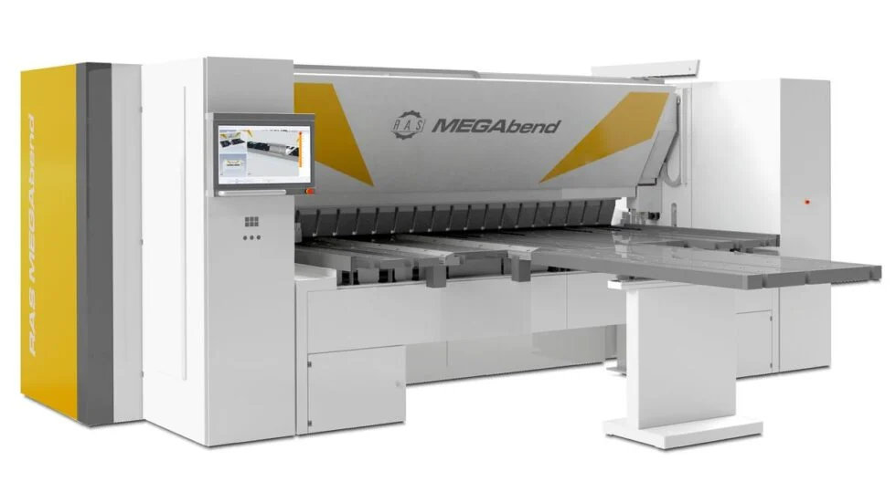
A panel bender (or panel folder) works the other way round. The sheet lies flat on a table, a blank holder clamps it along the bend line, and a bending blade swings up or down around the clamp to fold the flange — positive or negative — without the sheet ever being lifted. A manipulator rotates and repositions the sheet for the next side. Because the tooling does not press a die into the show face, there are no die marks, which matters on parts going straight to powder coat or made from pre-painted and film-protected sheet. Long panels with flanges on all four sides, return flanges, hems and closed profiles are exactly what panel benders are built for, and they run with very little handling labor once programmed.
Which machine for which part
| CNC press brake | Automated panel bender | |
|---|---|---|
| Best parts | Brackets, channels, small boxes, heavy parts, complex short bends | Long, wide panels: skins, doors, roofs, wraps, covers |
| Thickness | Thin sheet to heavy plate | Sheet gauges typical of enclosure work |
| Show-face marks | Possible; reduced with protective film tooling | None from tooling |
| Handling | Operator handles the part between bends | Machine manipulates the sheet |
| Setup | Tooling change per job | Largely tool-less between parts |
| Consistency on long panels | Good with crowning and measurement | Excellent; one clamp, one reference |
On a typical outdoor equipment cabinet, the doors, side skins and roof go to the panel bender, and the internal brackets, mounting rails, base channel and hinge parts go to the press brakes. Rolled shells and curved parts go to the plate roll (Part 5).
How FabTek runs it
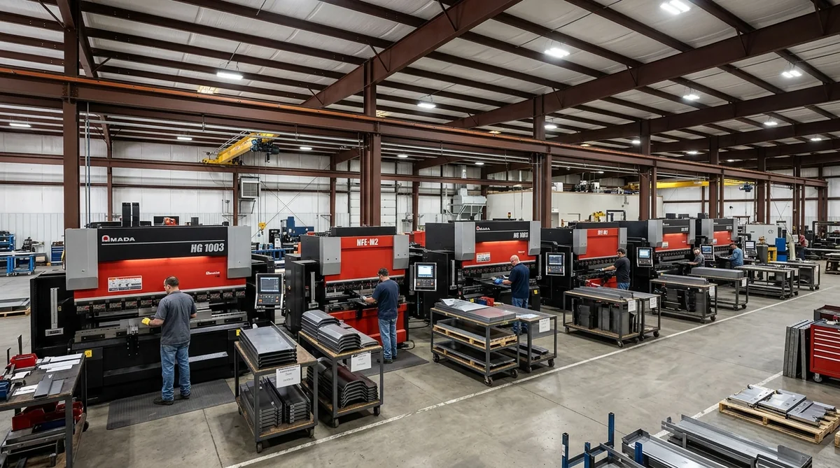
FabTek forms on three Amada CNC press brakes and seven supporting brakes — ten in all — with programmable back gauges, standard and radius tooling, hemming, offset and louver tooling for cabinet work, and film-protected tooling for finished surfaces. Long panels run on a RAS 76.40-2 MEGAbend automated CNC panel folder. Bend and fold sequences are programmed from FabTek engineering’s flat patterns and retained by part number, so repeat orders run without re-engineering, and formed parts move straight to hardware insertion, welding, powder coat and assembly on site. More on the Forming page.
Frequently asked questions
What is the difference between a press brake and a panel bender?
A press brake bends sheet by pressing it into a V-die with a punch, and the operator handles the part between bends; it suits thin to thick material and short or complex parts. A panel bender clamps the sheet flat and swings a blade to fold each flange, which suits long, wide panels, leaves no die marks and needs little handling.
How do you calculate press brake inside bend radius?
In air bending, the inside radius is set by the die opening, not the punch: it comes out at about 16 percent of the V-die opening for mild steel. With the common 8-times-thickness die, the inside radius is roughly equal to the material thickness.
What is the minimum flange length for a press brake bend?
Roughly 0.7 to 0.8 times the V-die opening for a 90-degree air bend. With an 8-times-thickness die, a 1/8 inch sheet needs a flange of at least about 3/4 inch; shorter flanges fall into the die and need special tooling.
How much tonnage does a press brake need?
A common estimate for air bending mild steel is tons per foot equals 575 times thickness squared divided by die opening, in inches. Bending 1/4 inch plate over a 2 inch die takes about 18 tons per foot. Stainless needs about 50 percent more, soft aluminum about half.