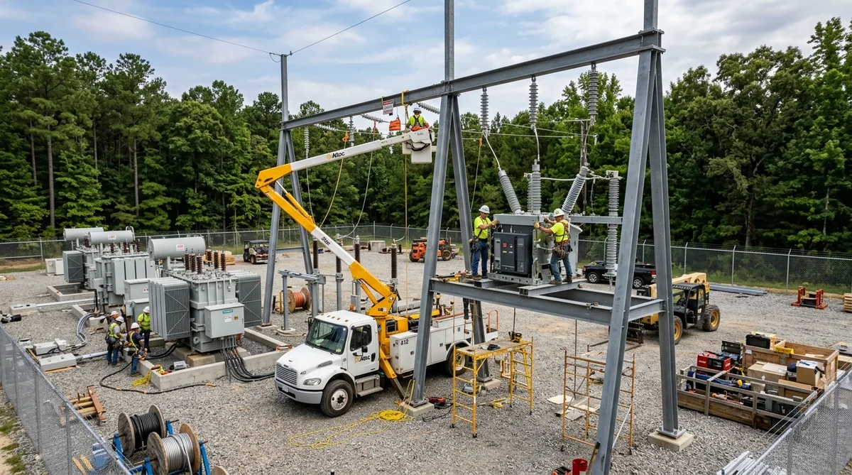
Everything in this series so far has been preparation for the day a crane lifts the first dead-end column off its dunnage and sets it on four anchor bolts. Part 6 is that day and the weeks that follow: how substation steel is erected, plumbed, bolted and grounded; how equipment is set on it; and why having the fabricator’s own crews do the work removes the handoff where most steel problems surface.
Have a substation steel package to quote? Call 601.892.5017 or email collin.t@fabtekindustries.com — send the layout and equipment list and we’ll turn it around fast.
- Erection begins with an anchor-bolt survey — misplaced bolts are the most common reason steel does not fit, and they are found before the crane arrives, not after.
- Sequence is dead-ends and gantries → bus supports → equipment stands → bus and insulators → equipment, paced by the crane and by clearances to anything energized.
- Structures are set, plumbed, shimmed and bolted to specification — snug-tight or pretensioned as the design calls for — then grounded.
- When the fabricator also erects, fit-up problems are the same company’s problem, and they get fixed the same day.
- From Load Request to Layout: How a Substation Project Starts
- The Long-Lead Equipment Order
- The Structures Package: Detailing Steel to Equipment
- Fabrication and Galvanizing: How Substation Steel Is Made
- Delivery Sequencing and Site Logistics
- Field Erection: How Substation Steel Goes Up (you are here)
- Energization and Commissioning
- The Change Order: Managing Late Design Changes
Before the first lift
Foundations have cured, and the anchor bolts projecting from them are the interface every structure depends on. The erector surveys each anchor-bolt group — location, projection, plumb, thread condition — against the foundation drawing and the fabricator’s base-plate detail. Bolts out of position are found now, while the fix is a survey note and a conversation with the foundation contractor, rather than on the hook with a dead-end column swinging. Steel bundles are confirmed against the erection drawing, hardware kits located, rigging inspected, the crane positioned for the first structures with its swing radius clear of overhead conductors and of anything energized in an adjacent yard.
Crew, crane and safety
A substation erection crew is small — a foreman, a crane operator, ironworkers to receive and connect steel at height, a ground crew rigging and staging. The crane is sized for the heaviest structure at its reach; a large gantry or a transformer set may bring in a second, larger crane for a day. Safety governs the pace: fall protection on every structure, tag lines on every load, exclusion zones under lifts, and — in brownfield yards — minimum approach distances to energized equipment, hold-offs coordinated with the utility, and a spotter on every lift near a live bus. Erection near energized equipment is where an experienced substation crew earns its rate; it is also why utilities ask erectors for their safety record before their price. FabTek’s substation assembly crews work under those rules nationwide.
The erection sequence
- Dead-ends, A-frames and gantries first. The tallest and heaviest structures, at the yard perimeter; they define the line terminations and set the crane’s access pattern for everything inside them.
- Bus supports next, along each bus run, plumbed and aligned to one another so the rigid bus they carry runs straight and level.
- Equipment stands, set at their foundation positions and oriented per the erection drawing so operating mechanisms and terminals face the right way.
- Miscellaneous steel — trench covers, conduit racks, platforms — as areas are finished.
- Bus and insulators on the structures, then equipment on the stands, then the transformer on its pad, typically last.
The sequence adapts to site constraints — a laydown area that must be cleared, a transformer heavy-haul date, an outage window in an existing yard — which is why the delivery plan in Part 5 is built with the erector.
Setting and plumbing
A structure is rigged at its designed pick points, lifted, guided over the anchor bolts and lowered onto leveling nuts or shims. Ironworkers install nuts loosely, and the structure is plumbed with a transit or laser and leveled at the base plate or the top plate — on an equipment stand, the top plate’s level and elevation are what matter, because the breaker’s operating mechanism and terminal heights depend on them. Shims are set, leveling nuts adjusted, and the structure is held while connections are made. Multi-piece structures are assembled on the ground where the crane and site allow and set as one lift, or built up in place with splice connections made at height. Bus-support runs are aligned along a string line so insulators land co-planar.
Bolting and grounding
Connections are bolted to the design specification. High-strength bolts are brought to snug-tight (all plies in firm contact) or pretensioned by turn-of-nut, calibrated wrench or tension-control bolts where the engineer requires it, with inspection per the applicable steel-construction specification. Anchor bolts get their top nuts, and base plates are grouted or left on leveling nuts per the design. Then each structure is grounded: the substation grounding grid connects to grounding pads the fabricator welded on before galvanizing, by exothermic or compression connectors, so every steel member is bonded — a safety requirement and an inspection item. Field drilling or welding on galvanized steel is avoided; where a modification cannot be avoided, the coating is repaired to ASTM A780.
Steel that was detailed to the mounting drawing, drilled on the beam line and surveyed to the anchor bolts goes up in a day. Steel that skipped any of those goes up in a week, with a drill.
Bus, insulators and equipment
With structures plumbed and bolted, station-post insulators are mounted to the bus-support plates and rigid bus is cut, fitted and welded or bolted into its fittings — expansion fittings where the run needs them. Equipment then comes: switches on their stands with operating mechanisms and pipes aligned, breakers set and bolted to top plates, arresters and instrument transformers on theirs, all to the OEM’s installation manual. Terminal connections, control cable in trench and conduit, and the transformer’s own assembly (radiators, bushings, conservator, oil processing) follow — often by the OEM’s field service and the utility’s crews. The steel, at this point, is invisible: it is simply where everything is.
Punch list and turnover
The erector walks the yard with the owner’s inspector: every structure plumb and bolted, every connection complete, every grounding pad connected, coating damage repaired, match-marks removed or acceptable, laydown area cleared. The punch list is closed, as-built erection drawings noted, and the yard is turned over for wiring, testing and commissioning — Part 7.
Fabricator-erected steel
Most substation steel is fabricated by one company and erected by another, and the boundary between them is where problems land: a stand that does not match its breaker, a splice that does not align, a missing gusset. Each is a phone call, a determination of whose fault, a repair or a reshipment, and a crane crew waiting. When the fabricator’s own crews erect — as FabTek’s do through substation assembly — the company that drilled the hole is the company standing at the anchor bolts, the fix is made the same day, and the schedule absorbs it. It also closes the loop: what the erector learns in the yard goes straight back to the detailer for the next package. It is the substation version of the single-source case we make throughout this site, and for an EPC it is one fewer subcontract to manage; see how we work with EPCs.
FabTek Industries fabricates substation structures for utilities, EPCs and data center developers — fabricated to the design and erected by our own crews, so fit-up, plumb, bolting and grounding are one company’s responsibility — under an ISO 9001:2015 quality system with AWS D1.1-certified welding, from four production sites in Hazlehurst, Mississippi, and our own crews handle field erection. See how we work with EPCs, with utilities, or send us the layout.
Frequently asked questions
In what order is substation steel erected?
Dead-end, A-frame and gantry structures at the perimeter first, then bus-support structures along each bus run, then equipment stands, then miscellaneous steel; bus and insulators are installed on the structures, equipment is set on the stands, and the transformer is typically set last.
What is the most common reason substation steel does not fit?
Anchor bolts out of position or projection relative to the base-plate detail. An anchor-bolt survey before the crane arrives finds these while the fix is simple, rather than with a structure on the hook.
How are substation structures bolted and grounded?
High-strength bolts are brought to snug-tight or pretensioned per the design, base plates grouted or left on leveling nuts as specified, and each structure is bonded to the grounding grid through grounding pads welded on before galvanizing, using exothermic or compression connections.
Why have the fabricator erect the substation steel?
Because the boundary between fabricator and erector is where fit-up problems surface. When one company details, fabricates and erects, a mismatch is resolved the same day without dispute, the crane keeps working, and field lessons feed back into the next package.