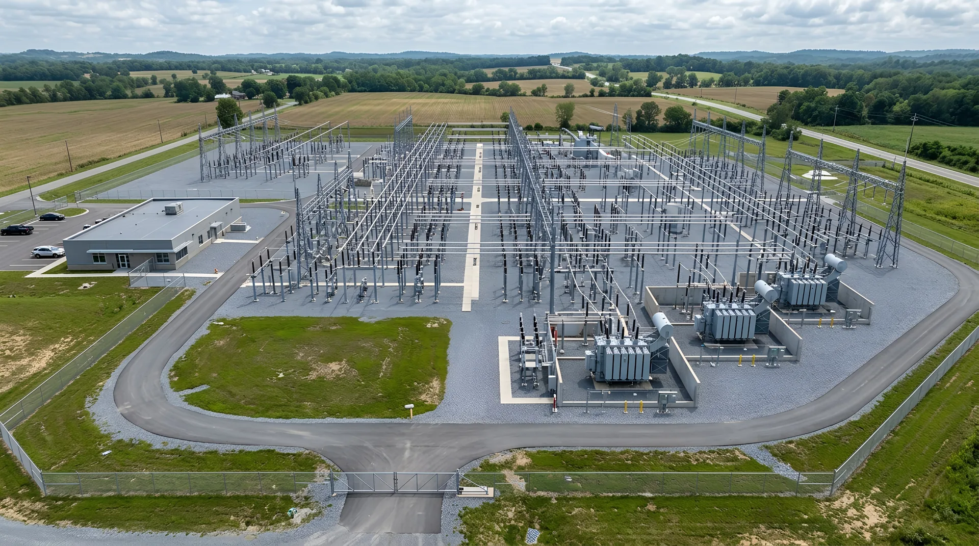
Every substation starts as a problem on a planning engineer’s screen: a new load that the existing system can’t carry, a reliability gap, a new line that needs a place to land, a transformer at the end of its life. This eight-part series follows a substation from that first problem through design, procurement, fabrication, delivery, erection and energization — and it is written for the people who buy and build them: utility engineers and project managers, EPCs, and the developers whose campuses depend on them. Part 1 is the beginning.
Have a substation steel package to quote? Call 601.892.5017 or email collin.t@fabtekindustries.com — send the layout and equipment list and we’ll turn it around fast.
- Substations originate from load growth, reliability needs, new transmission or asset replacement — increasingly from a single large customer such as a data center.
- Before design, planning and interconnection studies establish what has to be built; before construction, siting and permitting establish where and when.
- The one-line diagram defines the electrical scheme; the physical layout turns it into a yard with clearances, bus, equipment positions — and structures.
- The structures package should enter at layout, not at construction — it is the one long deliverable a project can pull forward.
- From Load Request to Layout: How a Substation Project Starts (you are here)
- The Long-Lead Equipment Order
- The Structures Package: Detailing Steel to Equipment
- Fabrication and Galvanizing: How Substation Steel Is Made
- Delivery Sequencing and Site Logistics
- Field Erection: How Substation Steel Goes Up
- Energization and Commissioning
- The Change Order: Managing Late Design Changes
Where a substation comes from
A substation is the grid’s interchange — where voltage is transformed, circuits are switched and protected, and power changes direction. We explained how one works in How a Substation Works. New ones get built for four reasons: load growth, when demand in an area exceeds what existing substations and feeders can serve; reliability, when a single-source area needs a second feed or a ring; new transmission, when a line is built and needs terminals and switching; and asset replacement, when a decades-old yard is rebuilt in place. In the current market a fifth reason dominates: a single large customer — a hyperscale data center, a battery plant, a reshored factory — requesting hundreds of megawatts at one site, which requires a dedicated substation and often a utility switching station to feed it. We covered that version in How a Data Center Gets Its Power.
Planning and interconnection studies
Before anyone draws a yard, the utility’s planning group models the system with the proposed load or line added: load flow, short-circuit, stability and contingency analysis that show whether existing lines and transformers can carry it and what has to be added if not. For loads and generation connecting through a regional transmission organization, the formal interconnection study process — feasibility, system impact, facilities — runs in parallel and can take years. The output is a scope: a new substation or an expansion, at a voltage, with a number of transformers and breakers, connected to specific lines, with a target in-service date. That in-service date, more than anything else, drives every decision that follows.
Siting and permitting
The yard has to be somewhere the lines can reach, on ground that can carry transformers and foundations, with road access for heavy-haul delivery, drainage that meets environmental rules, and setbacks that satisfy neighbors and zoning. Real estate, environmental review, wetlands and cultural-resource surveys, local permitting and sometimes state siting proceedings all happen here, and for transmission-connected projects, line routing and right-of-way acquisition can take longer than the substation itself. A common outcome is a site that is fixed before the design is final — which is why layouts are often constrained by a fence line that was drawn for a different reason.
The one-line
The one-line diagram is the electrical scheme on one sheet: incoming lines, breakers and switches, buses, transformers, feeders, and the protection and metering that watch them. It fixes the bus arrangement — single bus, main-and-transfer, ring bus, breaker-and-a-half, double-breaker-double-bus — which determines how many breakers, switches and bus sections exist, and therefore how much equipment and how much steel. A radial distribution substation with one transformer and a few feeders is a modest steel package; a 230 kV breaker-and-a-half yard serving a data center campus is a field of it. The one-line is also where redundancy is decided: two transformers instead of one, two lines instead of one, each adding equipment and structures.
The physical layout
The layout — general arrangement, plan and elevations — turns the one-line into a yard. Engineers place transformers, breakers, switches, arresters and instrument transformers according to electrical clearances (phase-to-phase, phase-to-ground, working clearances per the NESC and the utility’s standards), the bus arrangement, maintenance access, cable routing and the incoming line angles. Every piece of equipment gets a position and an elevation, and the bus gets a route between them. It is at this stage that the structures appear: the dead-ends where the lines terminate, the bus supports carrying rigid bus at its design height, the stands that put each breaker and switch at working elevation, the takeoff structures at the fence. The layout is the document from which a structures package can be defined, even before individual equipment is selected — and we explain that package in Part 3.
The one-line decides how many structures there are. The layout decides where they stand. The equipment decides how they are drilled. Order the steel at the second step, not the third.
Who does what
- The utility — owns the asset; planning, standards, protection, and either self-performs engineering and construction or hires it out. For a data center, the developer may build the customer side of the fence and the utility the other.
- The engineer of record / EPC — produces the layout, structural design, foundations, grounding, protection and control; on an EPC contract, also procures and builds. Our EPC page describes how we work with them.
- Equipment OEMs — transformers, breakers, switches, arresters, instrument transformers, switchgear, relays. They set the long-lead schedule (Part 2).
- The structures fabricator — fabricates and galvanizes dead-ends, bus supports, equipment stands, gantries and miscellaneous steel to the design (Part 4).
- The erector — foundations, steel erection, equipment setting, bus and wiring; sometimes the EPC’s own crews, sometimes a contractor, sometimes the fabricator’s (Part 6).
- Testing and commissioning — the utility’s or a contractor’s relay and equipment technicians who bring it to life (Part 7).
Where the steel enters
On most projects the structures package is procured after equipment is selected and the design is finalized — sensibly, because stands are drilled to specific equipment. But that puts a weeks-long fabrication and galvanizing cycle at the end of a years-long project, competing for the fabricator’s floor with every other project that did the same thing. The better sequence is to engage the fabricator at layout: budget the package from the general arrangement, reserve capacity against the in-service date, release the structures whose design is independent of equipment (dead-ends, bus supports, gantries, fence and misc.) as soon as they are final, and release the equipment stands as each OEM’s mounting drawings arrive. The steel becomes the deliverable that waits on site for the transformer, rather than the transformer waiting on the steel. That is the sequence this series follows; Part 2 starts with the equipment.
FabTek Industries fabricates substation structures and support steel — dead-ends, A-frames, bus supports, equipment stands, gantries, control enclosures and miscellaneous steel for utilities, EPCs and data center developers — quoted from the general arrangement, reserved against the in-service date, and released in the sequence the design and the site allow — under an ISO 9001:2015 quality system with AWS D1.1-certified welding, from four production sites in Hazlehurst, Mississippi, and our own crews handle field erection. See how we work with EPCs, with utilities, or send us the layout.
Frequently asked questions
Why are new substations being built?
Load growth, reliability needs, new transmission lines and replacement of aging assets — and increasingly, single large customers such as hyperscale data centers requesting hundreds of megawatts at one site, which require a dedicated substation and often a utility switching station.
What is the difference between a one-line diagram and a substation layout?
The one-line is the electrical scheme — lines, breakers, buses, transformers and protection — and fixes the bus arrangement and equipment count. The layout (general arrangement) places that equipment in a physical yard with clearances, elevations and bus routing, and is where the structures first appear.
When should the substation steel package be ordered?
At the layout stage. Structures whose design is independent of equipment (dead-ends, bus supports, gantries, miscellaneous steel) can be released once the layout is final; equipment stands are released as each OEM's mounting drawings arrive. Waiting until the design is complete puts a weeks-long fabrication cycle at the end of a years-long schedule.
Who fabricates substation structures?
Specialized structural fabricators that cut, drill, weld and hot-dip galvanize steel to the engineer's design. FabTek Industries fabricates substation structures and support steel for utilities, EPCs and data center developers from Hazlehurst, Mississippi, with its own crews for field erection.