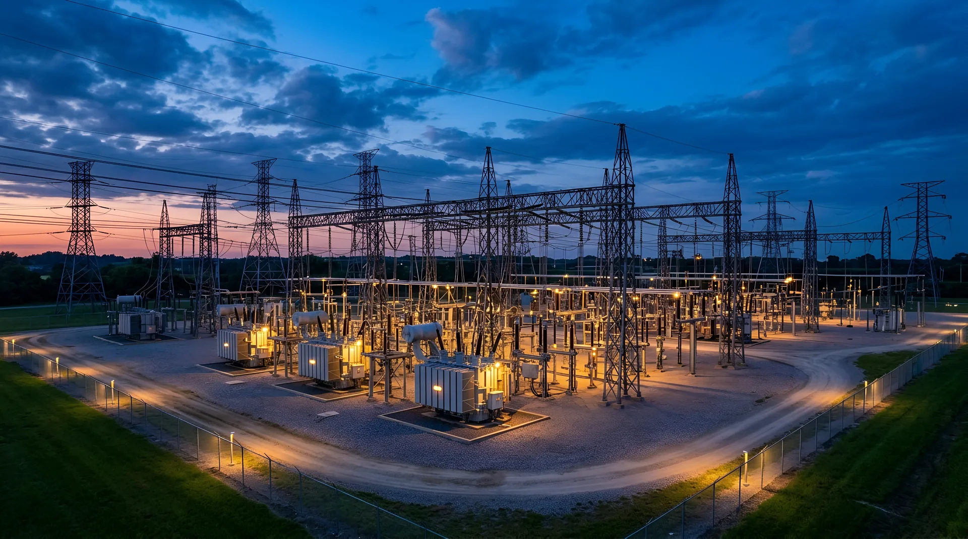
A substation is not finished when the last bolt is torqued. It is finished when the utility’s relay technicians have proven every protective function, every piece of equipment has passed its acceptance tests, the ground grid has been measured, and a switching order has brought the yard live one element at a time. Part 7 of this series is that process — and the handful of places where the fabricated steel, invisible by now, still matters.
Have a substation steel package to quote? Call 601.892.5017 or email collin.t@fabtekindustries.com — send the layout and equipment list and we’ll turn it around fast.
- Commissioning proves the yard works before it is live: wiring checks, equipment acceptance tests, relay functional tests, ground-grid measurement.
- Energization is staged by switching order — line, then bus, then transformer, then load — with checks at each step.
- The steel’s contribution to commissioning is clearances held, grounding continuity through every structure, and bus alignment that lets insulators and fittings sit unstressed.
- Punch items that surface here trace back to earlier parts of this series; a yard erected to plan has few.
- From Load Request to Layout: How a Substation Project Starts
- The Long-Lead Equipment Order
- The Structures Package: Detailing Steel to Equipment
- Fabrication and Galvanizing: How Substation Steel Is Made
- Delivery Sequencing and Site Logistics
- Field Erection: How Substation Steel Goes Up
- Energization and Commissioning (you are here)
- The Change Order: Managing Late Design Changes
What commissioning is
Commissioning is the systematic verification that a substation will do what it was designed to do — carry load, isolate faults, protect equipment, report to operators — before it is connected to the grid. It is performed by the utility’s or a contractor’s testing and commissioning group, under the utility’s standards, with the OEMs’ field service for major equipment. For the developer of a data center campus, it is the last gate before the utility can deliver power to the fence; we described that dependency in How a Data Center Gets Its Power.
Wiring and point-to-point
Before anything is tested, every control, protection and metering circuit is checked point-to-point against the schematics: each wire lands where the drawing says, each terminal is torqued, each label matches. CT and PT secondary circuits are verified for polarity and ratio, and CT circuits are confirmed not to be open. Where control cabinets and relay panels arrived pre-wired — from a shop that wired them to the drawing and bench-tested them — this phase is a confirmation rather than a hunt.
Equipment acceptance testing
| Power transformer | Oil sampling and dielectric tests after processing, insulation resistance and power factor, turns ratio, winding resistance, sweep frequency response where specified, bushing tests, cooling and tap-changer function, alarms and trips |
|---|---|
| Circuit breakers | Contact resistance, timing and travel, insulation and power factor, gas density and leak checks, operating-mechanism and trip/close function from the control circuit |
| Disconnect switches | Mechanical alignment and operation through the full stroke, contact engagement, auxiliary contact function, interlocks — alignment depends on the stand and mechanism being where the drawing put them |
| Instrument transformers & arresters | Ratio, polarity, insulation resistance; arrester leakage and insulation tests |
| Bus and insulators | Insulation resistance, connection resistance at fittings, visual and torque verification, expansion fittings free to move |
Protection and control
Relay settings are loaded and verified against the protection engineer’s settings sheet; each relay is tested with secondary injection to prove pickup, timing and logic; and functional trip tests confirm that each relay trips the breakers it is supposed to and nothing else. SCADA points are mapped and checked with operators. Communications to remote ends are proven. This is the most labor-intensive phase and the one that most often sets the energization date once the yard is built — which is why the fabrication and erection of the yard should have finished well before it.
Grounding and clearances
The ground grid is tested — typically by fall-of-potential or a clamp-on method — to confirm its resistance meets the design (per IEEE 80) so that step and touch potentials during a fault stay within safe limits. Every structure’s bond to the grid is verified for continuity: this is where the grounding pads the fabricator welded on before galvanizing and the connections the erector made in Part 6 are proven. Electrical clearances are measured in the finished yard against the design and the NESC — phase-to-phase, phase-to-ground, and working clearances — and depend directly on structures being at design height and bus being at design elevation.
The pre-energization walkdown
Owner, engineer, erector and commissioning lead walk every bay: temporary grounds removed, tools and materials cleared, guards and barriers in place, signage up, fence complete and grounded, oil containment closed, gates locked, drawings as-built. Punch items are cleared or formally accepted. Then the utility issues a switching order.
The energization sequence
- Line first. The incoming line is energized to the open line breaker or disconnect; voltage is checked and phasing confirmed against the system.
- Bus. Bus sections are energized through their breakers; PT voltages are checked and phasing verified across ties.
- Transformer. The transformer is energized from the high side with the low side open — inrush is watched, relays confirmed not to misoperate — and soaked, often for hours or a day, with oil samples and monitoring before load.
- Secondary and load. Low-side bus, then feeders or the customer’s circuits, picked up in steps while loads, voltages and temperatures are watched.
- In-service checks. Load readings compared with metering and relay quantities, infrared survey of connections under load, and a final review before the yard is declared in service.
By the time the switching order is read, the steel has done its job if nobody mentions it.
Where the steel shows up
Almost nowhere, which is the point. But three items in commissioning trace straight back to the structures package. Clearances: a bus support an inch low or a stand an inch high is a clearance measurement that fails the walkdown and a structure that gets shimmed or remade. Grounding continuity: a structure without a welded grounding pad, or one whose coating covers the bonding surface, is a continuity failure and a field repair. Alignment: a bus-support run that is not co-planar stresses insulators and fittings, shows up in connection-resistance readings and, later, in the infrared survey. Each of these was decided at detailing (Part 3), fabrication (Part 4) or erection (Part 6) — and each is why the fabricator’s process and the erector’s survey matter to a commissioning team that never meets either. What happens when the design changes after the steel is built is Part 8.
FabTek Industries fabricates substation structures and pre-wired control and relay cabinets for utilities, EPCs and data center developers — built to design height, with grounding pads welded before galvanizing and bus supports aligned for unstressed insulators — so commissioning finds no steel items on its list — under an ISO 9001:2015 quality system with AWS D1.1-certified welding, from four production sites in Hazlehurst, Mississippi, and our own crews handle field erection. See how we work with EPCs, with utilities, or send us the layout.
Frequently asked questions
What is substation commissioning?
The systematic verification, before a new substation is connected to the grid, that its equipment, protection, control and grounding work as designed: point-to-point wiring checks, equipment acceptance tests, relay setting and functional trip tests, ground-grid resistance measurement, a pre-energization walkdown and a staged energization under a switching order.
In what order is a substation energized?
Incoming line to the open breaker first, with voltage and phasing checked; then bus sections; then the transformer from the high side with the low side open, soaked and monitored; then secondary bus and feeders picked up in steps; followed by in-service checks including an infrared survey under load.
How is a substation ground grid tested?
Typically by a fall-of-potential test or clamp-on method to confirm grid resistance meets the IEEE 80 design so step and touch potentials during a fault are within safe limits, plus continuity checks of every structure's bond to the grid.
How do substation structures affect commissioning?
Through electrical clearances (structures at design height and bus at design elevation), grounding continuity (grounding pads welded on before galvanizing, bonded to the grid) and bus alignment (co-planar supports so insulators and fittings are unstressed). Each traces back to detailing, fabrication and erection.