Between the layout drawing and a truckload of galvanized steel sits the work that decides whether a substation bolts together: the structures package. Part 3 of this series is about how that package is designed and detailed — the loads it must carry, what governs each structure type, how stands are drilled to the equipment they hold, how steel is detailed so it survives the galvanizing kettle, and how to release it so fabrication starts before the design is entirely finished.
Have a substation steel package to quote? Call 601.892.5017 or email collin.t@fabtekindustries.com — send the layout and equipment list and we’ll turn it around fast.
- The package is dead-ends and A-frames, bus supports, equipment stands, gantries, control-house steel and miscellaneous — each with its own governing load.
- Design follows ASCE 113: conductor tension, short-circuit forces, wind, ice, seismic and — often decisive — deflection limits that protect equipment and clearances.
- Equipment stands are detailed to the OEM’s mounting drawing; get those drawings early and the stands leave the critical path.
- Detail for the kettle — vents, drains, hanging points, no sealed cavities — and run a disciplined shop-drawing cycle; most field problems trace to one or the other.
- From Load Request to Layout: How a Substation Project Starts
- The Long-Lead Equipment Order
- The Structures Package: Detailing Steel to Equipment (you are here)
- Fabrication and Galvanizing: How Substation Steel Is Made
- Delivery Sequencing and Site Logistics
- Field Erection: How Substation Steel Goes Up
- Energization and Commissioning
- The Change Order: Managing Late Design Changes
What the package contains
A structures package is every fabricated steel item in the yard other than the equipment itself. Typically: dead-end and A-frame structures terminating incoming and outgoing lines; bus-support structures carrying rigid or strain bus and its insulators; equipment stands for breakers, switches, arresters, CTs, PTs and CCVTs; gantry, goalpost and takeoff structures; control-house and switchgear-enclosure steel; and miscellaneous — cable trench covers and supports, conduit racks, platforms and ladders, transformer firewalls, fence posts and gates. FabTek fabricates the full range as substation structures and support steel; our general buyer’s guide is Substation Steel: A Buyer’s Guide.
The design basis
Substation structures in the United States are designed to ASCE 113, Substation Structure Design Guide, alongside the steel design codes and the owner’s standards. The loads it addresses:
- Conductor and shield-wire tension — for dead-ends, the full line tension under the design weather cases, including unbalanced and broken-conductor conditions.
- Short-circuit forces — the electromagnetic forces between bus conductors during a fault, transmitted to bus supports and insulators; calculated per IEEE 605 for rigid bus.
- Wind and ice — on structure, equipment and conductors, per the site’s design criteria.
- Seismic — per IEEE 693 for equipment qualification and the site seismic category, affecting stand stiffness and anchorage.
- Equipment operation and maintenance — switch operating loads, breaker operating forces, and live loads on platforms.
- Deflection — often the governing criterion. ASCE 113 sets deflection limits by structure class so that equipment operates correctly, clearances are held and insulators are not overstressed; many stands are sized for stiffness rather than strength.
The engineer of record produces design drawings — member sizes, connection concepts, base reactions for the foundation designer — from which the fabricator’s detailer produces shop drawings.
Structure by structure
| Dead-end / A-frame | Governed by conductor tension and unbalanced cases. Heavy wide-flange or tubular columns, cross-arms with insulator attachment plates, often A-frame or H-frame with knee braces. Detailing focus: attachment-plate geometry and hole pattern for insulator hardware, base plates and anchor bolts, splice locations for shipping. |
|---|---|
| Bus support | Governed by short-circuit force and deflection. Single columns or beam-and-column frames with insulator mounting plates at bus height. Detailing focus: insulator bolt circle, plate levelness, column plumb, and consistent height across a bus run. |
| Equipment stand | Governed by deflection, seismic and operating loads. Built to the OEM’s mounting drawing: top-plate bolt pattern and hole size, working height to set terminals at design elevation, operating-mechanism mounts for switches, grounding pads. Detailing focus: exact bolt pattern, top-plate flatness, orientation marks. |
| Gantry / takeoff | Governed by tension and wind; tallest steel in the yard. Detailing focus: field splices, climbing provisions, shield-wire attachments. |
| Control-house & enclosure steel | Building frames, platforms, cable-entry supports; often paired with walk-in switchgear enclosures. |
| Miscellaneous | Trench covers and frames, conduit racks, platforms, ladders, firewalls, fence. Governed by live load and durability. Detailing focus: quantities, kitting, coating. |
Connections and hardware
Substation connections are bolted wherever possible, so that galvanizing is done on shop-welded sub-assemblies and the field does no welding on coated steel. High-strength bolts (F3125 / A325 class) in standard holes (1/16″ over bolt diameter) for structural connections; slotted holes where field adjustment is intended; F1554 anchor bolts sized by the foundation designer and set to a template the fabricator supplies. Hardware is galvanized to ASTM A153. The detailer’s job is to make every connection buildable with the crane and the crew on site: accessible bolt positions, splices at trucking limits, match-marks that make sense at 30 feet in the air.
Detailing to equipment
This is where most stand problems originate. A breaker stand detailed to a “typical” pattern and then matched to a different breaker is a field-drilling job on galvanized steel — slow, coating-damaging and often out of tolerance. The discipline is simple: no equipment stand is released for fabrication until the OEM’s approved mounting drawing is in hand, and the shop drawing references that drawing by number and revision. When equipment is dual-sourced or not yet awarded, stands can be designed for load and height and held, or detailed with a bolt pattern that accommodates both approved manufacturers if the engineer allows. As Part 2 argued, mounting drawings usually exist a year or more before the equipment ships — ask for them.
Detailing for galvanizing
Hot-dip galvanizing immerses the finished steel in molten zinc at roughly 830 °F, and steel that is not detailed for that trip comes back damaged or does not come back at all. The fabricator’s detailer applies ASTM A385 practice: vent and drain holes in every closed or semi-closed section so zinc flows in and air and zinc flow out (an unvented tube can rupture in the kettle); no overlapping plates without weep holes, which trap pickling acid and later bleed rust; hanging or lifting points so the piece can be dipped at the right angle; sizing within the kettle, splitting oversize structures at bolted splices; and weld consistency, because weld metal and base metal take zinc differently. We compared coating systems in Galvanizing vs. Paint; Part 4 goes through the kettle itself.
A substation stand has two customers: the breaker that bolts to it and the galvanizer that dips it. Detail for both or you will meet one of them again in the field.
Shop drawings and review
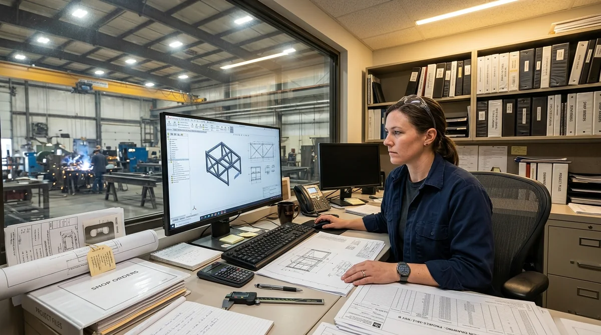
The fabricator’s detailer converts design drawings into shop drawings: every member, every hole, every weld, every piece mark, with a bill of materials and an erection drawing. The engineer of record reviews them for conformance to design intent — not to re-engineer, but to catch a wrong plate thickness or a missed bolt pattern. A disciplined cycle — agreed turnaround times, a single point of contact, revisions tracked by cloud and letter — keeps this from consuming the schedule float the early release bought. FabTek details in 3D so bolt patterns, clearances and erection sequence can be checked in the model before steel is cut; the spec-package basics are in What Belongs in a Build-to-Print Spec Package.
Release sequence
Release the package in the order the design allows and the site needs: first, structures independent of equipment and needed first in erection — dead-ends, gantries, bus supports, fence and trench; then equipment stands as each mounting drawing is approved; then miscellaneous steel and platforms; then control-house steel. Each release carries its own shop-drawing approval, fabrication, galvanizing and delivery, so the fabricator’s line runs continuously rather than in one late surge, and the erector receives steel in the sequence of Part 5.
FabTek Industries fabricates complete substation structures packages detailed in 3D from the engineer’s design and the OEMs’ mounting drawings for utilities, EPCs and data center developers — detailed for galvanizing to ASTM A385 practice, processed on a robotic beam line, welded to AWS D1.1, hot-dip galvanized to ASTM A123 and released in erection sequence — under an ISO 9001:2015 quality system with AWS D1.1-certified welding, from four production sites in Hazlehurst, Mississippi, and our own crews handle field erection. See how we work with EPCs, with utilities, or send us the layout.
Frequently asked questions
What design standard governs substation structures?
ASCE 113, Substation Structure Design Guide, together with the applicable steel design codes and the owner's standards. It addresses conductor tension, short-circuit forces (IEEE 605 for rigid bus), wind, ice, seismic (with IEEE 693 for equipment) and deflection limits, which frequently govern stand and bus-support design.
What is included in a substation structures package?
Dead-end and A-frame structures, bus-support structures, equipment stands for breakers, switches, arresters and instrument transformers, gantry and takeoff structures, control-house and enclosure steel, and miscellaneous items such as cable trench covers, conduit racks, platforms, firewalls and fence.
How are equipment stands detailed?
To the equipment manufacturer's approved mounting drawing — base footprint, bolt pattern, hole size, working height and terminal elevation — referenced by drawing number and revision on the shop drawing. Stands should not be released for fabrication until that drawing is in hand.
What does 'detailing for galvanizing' mean?
Following ASTM A385 practice so steel survives the hot-dip kettle: vent and drain holes in closed sections, weep holes at overlapping plates, hanging points, sizing pieces to fit the kettle with bolted splices, and consistent welds — preventing ruptured tubes, trapped acid and coating defects.