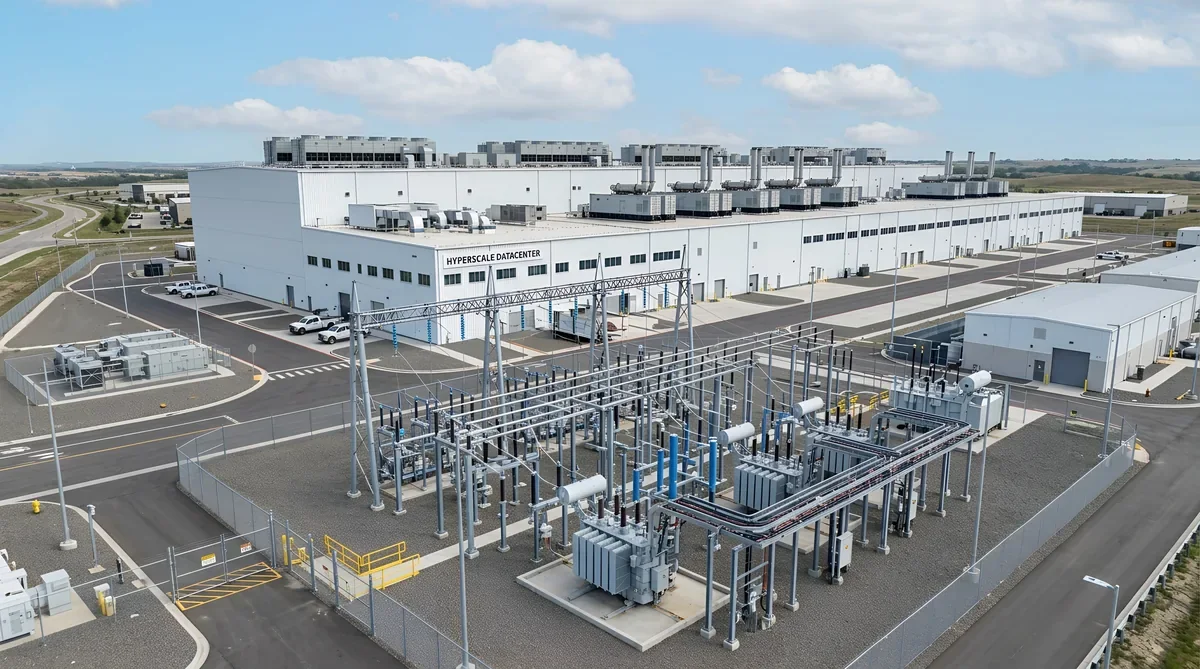
Before a single server is racked, a data center has to solve a harder problem than computing: getting hundreds of megawatts of reliable power to a specific piece of land. This part of the series follows the electricity from the regional grid to the campus property line — the interconnection process, the transmission tap, the on-site substation — and looks at the galvanized steel and control enclosures that every one of those steps depends on.
Building or supplying a data center? Call 601.892.5017 or email collin.t@fabtekindustries.com — send a drawing, a one-line, or a scope and we’ll respond fast.
- Power availability now drives site selection. Developers chase “powered land” — parcels with transmission access and interconnection capacity — before they chase fiber or tax incentives.
- Utility interconnection for a large load takes years, not months, and the studies, upgrades and large power transformers set the schedule for everything else.
- The campus substation steps transmission voltage (115–345 kV) down to medium voltage (typically 34.5 or 13.8 kV) for distribution across the site — usually with redundant feeds and transformers.
- Every piece of that substation stands on fabricated, hot-dip galvanized steel — dead-ends, A-frames, bus supports and equipment stands — which can be built while the long-lead equipment is still in the queue.
- What's Inside a Data Center? Anatomy of a Hyperscale Campus
- How a Data Center Gets Its Power: Grid Interconnect to Fence Line (you are here)
- Inside the Electrical Room: Switchgear, UPS and Bus Duct to the Rack
- Where Data Center Builds Get Stuck: The Real Bottlenecks
- Sourcing Fabricated Power Equipment for a Data Center: A Buyer's Guide
Step one: siting the campus around power
Ten years ago, data center site selection was about fiber routes, land cost and tax incentives. Today the first question is simpler and harder: where can we get several hundred megawatts, and when? The industry even has a term for the answer — “powered land,” meaning parcels with existing or committed transmission capacity. Developers will accept a less convenient location if the utility can commit to power on a schedule.
That is a large part of why campuses have spread from the traditional hubs into regions with available transmission and generation — including central Mississippi, where a $25 billion wave of hyperscale investment landed alongside the largest grid upgrade in the local utility's history. The power came first; the buildings followed.
Step two: the utility interconnection process
A data center cannot simply plug into the grid. It has to be studied, approved and physically connected by the utility and, for the largest loads, coordinated with the regional transmission organization. The process generally runs like this:
- Load request and feasibility study — the developer tells the utility how many megawatts it needs and when. The utility models whether the local transmission system can carry that load without overloading lines or transformers.
- System impact and facilities studies — engineers determine what has to be built: new transmission lines, a new or expanded substation, upgraded breakers, sometimes new generation. These studies identify the large power transformers, which are the longest-lead item on the entire project.
- Agreements and cost allocation — the parties settle who pays for what. Many utilities now have dedicated large-load tariffs that require minimum contract terms and up-front commitments from data center customers so that other ratepayers are protected if the load never materializes.
- Construction and energization — the utility builds its side of the fence, the developer builds its side, and the two are tested and energized together.
The honest timeline for all of that is measured in years. Transmission line permitting alone can take longer than the entire building construction, and a 230 kV or 345 kV power transformer ordered today may not ship for two to four years. We break down each of those constraints in Part 4. The practical consequence is that developers now begin the interconnection process before they have a finished design, and try to place every long-lead order as early as the studies allow.
Step three: the transmission tap
Physically, the power arrives on high-voltage transmission — commonly 115 kV, 138 kV, 230 kV or 345 kV depending on the region and the size of the load. The line either loops through a new utility switching station built for the campus or taps directly into the customer substation. At the point where the conductors come down, they terminate on dead-end structures: heavy galvanized steel frames, often H-frame or A-frame configurations, engineered to hold the full tension of the incoming line. From there the conductors run through disconnect switches and circuit breakers mounted on equipment stands, and along rigid or strain bus supported on bus-support structures.
For very large campuses the utility will often build a full ring-bus or breaker-and-a-half switching station so that the campus can lose any single line or breaker and stay energized. That redundancy roughly doubles the equipment count — and the steel count — compared with a simple tap. If you want the general version of how this equipment works together, we walked through it in How a Substation Works.
Step four: the campus substation
The on-site substation does one main job: step transmission voltage down to a medium voltage that can be distributed around the campus and into each building — typically 34.5 kV or 13.8 kV in the U.S. Its main components are:
- Power transformers — the large units that do the step-down, each sitting in a welded steel tank on a concrete pad with oil containment. A hyperscale campus may need several, sized so that the loss of any one still leaves enough capacity for the full load (N+1 or 2N).
- High-voltage switching — circuit breakers, disconnect switches, surge arresters and instrument transformers, all mounted on galvanized stands and connected by rigid bus on bus supports.
- Medium-voltage switchgear — the transformer secondaries land in metal-clad switchgear, either outdoors in a walk-in NEMA 3R enclosure or inside an electrical building, which then feeds the campus distribution circuits.
- Control house and protection — relays, meters, SCADA and communications equipment in a control building or in relay and control cabinets, with cable trench connecting it all.
You cannot compress a transformer lead time. What you can do is have every piece of steel around it fabricated, galvanized and on site before it arrives.
The steel that holds it all up
None of the equipment above works without structure, and all of that structure is fabricated. A campus substation is essentially a field of galvanized steel:
- Dead-end and A-frame structures that terminate the incoming lines and carry the strain.
- Bus-support structures — the columns and beams that carry rigid bus and insulators across the yard.
- Equipment stands for breakers, disconnect switches, arresters, CTs and PTs, each built to the equipment manufacturer's bolt pattern.
- Goalpost, gantry and takeoff structures where lines enter or leave the yard.
- Control enclosures, relay cabinets and junction boxes that protect the electronics from the weather.
Because this steel lives outdoors for decades, it is almost always hot-dip galvanized rather than painted — we explain the tradeoffs in Hot-Dip Galvanizing vs. Paint for Substation Steel. It has to be fabricated to tight bolt-hole tolerances so that equipment from several different manufacturers lands on it without field modification, and it has to be delivered in erection sequence so the field crew is never waiting on a truck.
This is also the part of the project with the most schedule flexibility working in the developer's favor. A dead-end structure or bus support can be fabricated in weeks, not years. Ordering the substation steel package as soon as the layout is fixed — rather than waiting for the transformer delivery date — is one of the few ways to pull float back into a data center power schedule. Some owners go further and have the fabricator's own crews handle field erection, which removes one more handoff.
Step five: across the campus
From the substation, medium-voltage feeders run — usually underground in duct bank — to each building on the campus. At the building, the feeders land in medium-voltage switchgear and then in unit substations or pad-mounted transformers that step the power down again, to the 480 V or 415 V used inside the electrical rooms. Each of those pad-mounts sits in a NEMA 3R transformer cabinet; each set of switchgear sits in an enclosure; and in a 2N design there are two of everything, on physically separated paths so a single fault, fire or maintenance outage cannot take both down.
That is where this part of the story hands off. Once the power crosses into the electrical room, it enters the chain of switchgear, UPS, bus duct and PDUs that Part 3 follows all the way to the server rack.
Behind-the-meter options and what they don't change
With interconnection queues stretching out, some developers are building their own generation — gas turbines or reciprocating engines behind the meter, fuel cells, large battery energy storage systems — to get a campus running before the grid connection is complete, or to supplement it afterward. Others are co-locating next to existing power plants to shortcut the transmission problem entirely.
Every one of those approaches still needs the same downstream infrastructure. Generation has to step up or down through transformers, land in switchgear, and be distributed through the same enclosures, bus duct and support steel as grid power. If anything, on-site generation adds equipment: more switchgear enclosures, more transformer tanks, more structural steel for the plant itself. The interconnection problem can be worked around; the fabrication content cannot.
The fabrication perspective
Seen from a fabricator's floor, the journey from grid to fence line is a sequence of steel and enclosures wrapped around a handful of long-lead electrical components: substation structures and transmission structures for the tap and the yard, transformer tanks for the step-down units, switchgear enclosures and control cabinets for protection and switching, and transformer cabinets at every building.
FabTek Industries fabricates all of it domestically — cut on fiber laser and robotic plasma, formed on CNC press brakes, welded by AWS-certified welders under an ISO 9001:2015 quality system, and coordinated through hot-dip galvanizing or powder coat — across four production sites in Hazlehurst, Mississippi, with field crews available for on-site erection. If you are planning a campus substation or a utility switching station to serve one, send us the layout and we'll quote the steel package early enough to keep it off your critical path.
Frequently asked questions
How long does it take to connect a data center to the grid?
For a large campus, utility interconnection typically takes several years. The feasibility, system impact and facilities studies, transmission permitting, and the two-to-four-year lead time on large power transformers all contribute. Developers now begin the process before final design and place long-lead orders as early as the studies allow.
What voltage does a data center connect at?
Hyperscale campuses connect at transmission voltage — commonly 115, 138, 230 or 345 kV — and step it down on site to a medium voltage such as 34.5 or 13.8 kV for distribution across the campus. Inside each building it is stepped down again to 480 V or 415 V.
What is 'powered land' in data center development?
Powered land is a site with existing or committed transmission capacity and utility interconnection, so a developer can energize a campus on a known schedule. Power availability has become the primary driver of data center site selection.
What is in a data center substation?
Large power transformers in welded steel tanks, high-voltage breakers and disconnect switches on equipment stands, rigid bus on bus-support structures, dead-end structures terminating the incoming lines, medium-voltage switchgear in outdoor enclosures or an electrical building, and a control house — all standing on hot-dip galvanized fabricated steel.
Can substation steel be fabricated before the transformers arrive?
Yes, and it should be. Dead-ends, A-frames, bus supports and equipment stands can be fabricated and galvanized in weeks once the layout and equipment bolt patterns are fixed, so ordering the steel package early is one of the few ways to recover schedule on a data center power project.