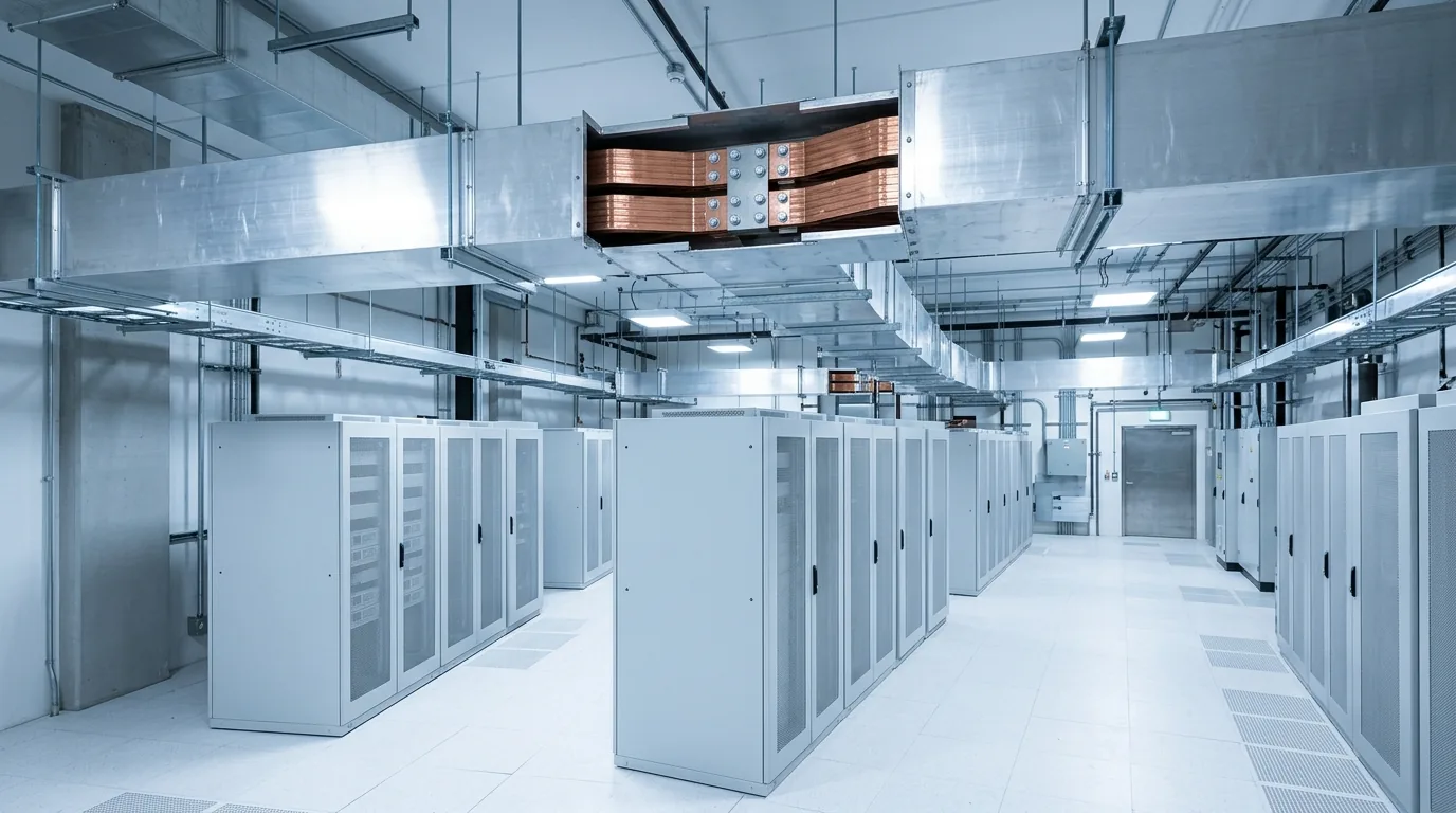
Part 2 followed power from the grid to the fence line. This part picks it up inside the building — through the electrical rooms that turn a medium-voltage feed into thousands of clean, protected, redundant circuits at the rack. Every stage of that chain is electrical equipment wrapped in fabricated metal, and the way the chain is designed for redundancy is what makes a data center one of the most enclosure- and bus-duct-intensive buildings on earth.
Building or supplying a data center? Call 601.892.5017 or email collin.t@fabtekindustries.com — send a drawing, a one-line, or a scope and we’ll respond fast.
- The chain runs MV switchgear → unit substation transformer → LV switchgear → UPS → distribution → bus duct → PDU → rack, with generators paralleled in at the switchgear.
- Redundancy multiplies equipment. A 2N design has two complete, independent paths — roughly double the switchgear, enclosures, transformers and bus duct of a single-path building.
- At data center currents, bus duct replaces cable — rigid, tap-able busway is the practical way to move 1,600–6,000+ amps and reconfigure a hall.
- AI rack densities push the industry toward 415 V distribution, higher-amperage busway and liquid cooling — all of which mean more, and heavier, fabricated metal.
- What's Inside a Data Center? Anatomy of a Hyperscale Campus
- How a Data Center Gets Its Power: Grid Interconnect to Fence Line
- Inside the Electrical Room: Switchgear, UPS and Bus Duct to the Rack (you are here)
- Where Data Center Builds Get Stuck: The Real Bottlenecks
- Sourcing Fabricated Power Equipment for a Data Center: A Buyer's Guide
The one-line diagram, in plain English
Every data center's power system is summarized on a one-line diagram — a schematic that shows each piece of equipment as a box and each connection as a single line. Read from top to bottom, a typical hyperscale one-line looks like this:
- Utility feed at medium voltage (34.5 or 13.8 kV) arrives from the campus substation — two feeds in a redundant design.
- Medium-voltage switchgear receives, protects and switches those feeds.
- Unit substation transformers step the power down to 480 V (or, increasingly, 415 V).
- Low-voltage switchgear and switchboards divide the power into large branch circuits.
- UPS systems condition the power and bridge the gap to generator start.
- Distribution boards and bus duct carry it into the data hall.
- PDUs, RPPs and busway tap-offs make the final split to individual racks.
- Standby generators tie in at the switchgear through paralleling gear and automatic transfer.
Now walk that chain one box at a time.
Medium-voltage switchgear
The medium-voltage gear is the building's front door for power. Metal-clad switchgear lineups house vacuum circuit breakers, protective relays and bus in compartmentalized steel sections, so a fault in one compartment is contained. They sit either indoors in the main electrical room or outdoors in a walk-in, weatherproof NEMA 3R switchgear enclosure — a fabricated steel building with its own lighting, heating and ventilation, delivered with the gear already installed and wired.
The enclosure specification here is not cosmetic. Gauge, weld quality, gasketing, door hardware and finish determine whether the gear inside survives 20 years of weather, and arc-resistant designs add pressure-relief and reinforcement requirements on top. We covered the details in Switchgear Enclosures for Hyperscale Builds and the rating system in NEMA 3R vs. 4 vs. 4X.
Unit substations and step-down transformers
From the MV switchgear, feeders run to unit substation transformers — often 2,500 to 3,750 kVA each, in dry-type or liquid-filled construction — that step the power down to utilization voltage. In a 2N building there are two independent sets of them, physically separated. Dry-type units sit in ventilated transformer enclosures; liquid-filled units sit in welded tanks with radiators, and outdoor pad-mounts live in NEMA 3R cabinets. A large campus can require dozens of these transformers per building, which is one reason distribution transformer lead times have stretched alongside the large power units — a topic we cover in Part 4.
Low-voltage switchgear, switchboards and UPS
The transformer secondaries land in low-voltage switchgear — draw-out power circuit breakers in steel sections — and switchboards that split the power into circuits of a few thousand amps each. This is where the building's redundancy is actually implemented: tie breakers, automatic throw-overs and static transfer switches let the operator move load between the two paths for maintenance or after a fault.
Downstream sits the UPS. A double-conversion UPS rectifies the incoming AC to DC, charges a battery string, and inverts it back to perfectly clean AC — so a sag, surge or momentary outage upstream never reaches the servers. When the utility fails, the batteries carry the full load for the 10–15 seconds the generators need to start and synchronize. UPS systems are modular cabinets; the batteries (increasingly lithium-ion) live in their own cabinets or in dedicated battery rooms with steel racking and containment. All of it is fabricated sheet metal and structural steel, and a great deal of the low-voltage gear is delivered with wiring harnesses and integrated wire-out already installed so the electrical contractor is landing feeders, not building panels.
Standby generators
Every hyperscale building carries enough diesel generation to run the entire facility indefinitely with fuel deliveries — in 2N or N+1 arrangements, meaning either a full duplicate set or at least one spare unit beyond what the load requires. The generators live in the yard in steel enclosures, and their output is combined in paralleling switchgear — another enclosure-housed lineup — before tying into the building's LV or MV gear through automatic transfer. Generator lead times have stretched to two years or more in the current market, so, as with transformers, the enclosures and structural bases are frequently fabricated well ahead of the engines themselves.
Bus duct and busway: why cable stops making sense
Here is where a data center departs from a normal commercial building. At a few hundred amps, power moves in cable. At 4,000 amps, moving power in cable means dozens of parallel conductors per phase, enormous conduit banks and terminations that take days to make up. A rigid bus duct — copper or aluminum bars in a fabricated steel or aluminum housing — moves the same current in a fraction of the footprint, with far fewer connections and predictable impedance.
Inside the building, bus duct does two jobs. Feeder bus duct — non-segregated phase bus in heavy-gauge housings, rated 1,600 to 6,000 amps and up — connects transformers to switchgear and switchgear to distribution, often running through walls and up mezzanines with fabricated elbows, offsets and expansion sections. Overhead busway then runs down each row of the data hall with tap-off points every few feet, so a new rack can be powered by plugging in a tap box rather than pulling a new circuit. That plug-and-play flexibility is why nearly every new hall is designed around busway instead of under-floor whips.
The fabrication requirements are demanding: precise housing dimensions so sections align across a 300-foot run, clean welds and finishes that don't shed debris into live bus, and tap-box and joint geometry that matches the OEM's bus stack exactly. It is the reason FabTek stood up a dedicated datacenter bus duct line, and we cover what to specify in Datacenter Bus Ducts: A Buyer's Guide.
A data center is not a building that happens to have a lot of switchgear. It is a power distribution system with a data hall attached — and every component in that system is delivered inside fabricated metal.
Redundancy topologies, and what they do to the equipment count
The vocabulary — N, N+1, 2N, 2N+1 — describes how much spare capacity the design carries. N is exactly what the load needs. N+1 adds one spare unit of each component. 2N duplicates the entire path from utility to rack, so an entire electrical room can be offline and the hall stays up. 2N+1 duplicates the path and adds a spare on each side. The Uptime Institute's Tier system formalizes this: Tier III facilities are concurrently maintainable, meaning any component can be taken down for maintenance without affecting the load; Tier IV facilities are fault-tolerant, surviving any single unplanned failure.
The fabrication consequence is arithmetic. A 2N building has two of every switchgear lineup, two sets of unit substations, two UPS plants, two bus duct risers and two busways down every row. Compared with a single-path commercial building of the same load, that is roughly twice the switchgear enclosures, twice the transformer cabinets and roughly twice the bus duct, before counting the generator yard. Multiply by the number of buildings on a campus and the volume becomes clear — and it is why a fabricator's ability to run this work on dedicated production lines with reserved capacity, rather than as one-off jobs, matters to the schedule.
What AI density is changing
The move from 10 kW racks to 100 kW racks is reshaping the electrical room in three ways that all land on fabricators. First, voltage: more halls are distributing at 415 V rather than 480/208 V to reduce a conversion stage, which changes transformer specs and busway ratings. Second, current: busway in AI halls is climbing from 400–800 A per row toward 1,200 A and higher, with correspondingly heavier housings and tap boxes. Third, cooling: air can't remove 100 kW from a rack, so direct-to-chip liquid cooling brings coolant distribution units, manifolds, piping and their frames and skids into the hall — a new category of fabricated content that didn't exist in the last generation of buildings.
The fabrication perspective
Every box on the one-line diagram is a piece of electrical equipment delivered inside fabricated metal: switchgear in NEMA-rated enclosures, transformers in cabinets and tanks, power in bus duct, control circuits in harnesses and wired panels. Most of it is build-to-print work for switchgear OEMs, electrical contractors and EPCs, and most of it has to arrive in sequence with long-lead gear that has been on order for years.
FabTek Industries builds that metal — and does the electrical assembly to go with it — under one roof in Hazlehurst, Mississippi: laser-cut, CNC-formed, AWS-welded, powder-coated and wired to print under an ISO 9001:2015 quality system, with a dedicated bus duct line for datacenter work. Having metal and electrical in one shop removes the handoff that most often slips a schedule, which we explain in Single-Source Datacenter Power. If you're building or supplying the electrical rooms for a campus, send us the one-line and the enclosure drawings — we'll tell you quickly what we can build and when.
Frequently asked questions
What is the power chain inside a data center?
Medium-voltage switchgear receives the campus feed; unit substation transformers step it down to 480 or 415 V; low-voltage switchgear and switchboards divide it; UPS systems condition it and bridge outages; bus duct carries it into the hall; and PDUs or busway tap-offs deliver it to each rack. Standby generators tie in at the switchgear.
What does 2N mean in a data center?
2N means two complete, independent power paths from the utility to every rack, so an entire electrical room can be offline for maintenance or a fault and the hall stays up. It roughly doubles the switchgear, transformers, enclosures and bus duct compared with a single-path building.
Why do data centers use bus duct instead of cable?
At thousands of amps, cable requires many parallel conductors, large conduit banks and slow terminations. Bus duct moves the same current in a compact fabricated housing with fewer connections, and overhead busway lets racks be added by plugging in tap boxes rather than pulling new circuits.
How long does a data center UPS carry the load?
Typically 10–15 seconds — long enough for the standby generators to start, reach speed and synchronize. Some designs carry several minutes of battery for additional margin.
How is AI changing data center electrical design?
Higher rack densities are pushing distribution toward 415 V, raising busway ratings to 1,200 A and above per row, and requiring direct-to-chip liquid cooling, which adds coolant distribution units, manifolds and support skids to the data hall.