A formed part is cut flat, so someone has to work out how long the flat blank must be for the bends to land in the right place. That calculation is the flat pattern, and it rests on three terms that show up in every CAD sheet-metal module: K-factor, bend allowance and bend deduction. Here is what they mean, the formulas, and a worked example.
Want a design-for-fabrication review on your drawing? Call 601.892.5017 or email collin.t@fabtekindustries.com — send the model or drawing and our engineers will mark it up.
- Bend allowance is the length of the neutral axis through the bend: BA = (π/180) × A × (R + K × T), with bend angle A in degrees, inside radius R, thickness T and K-factor K.
- K-factor locates the neutral axis as a fraction of thickness from the inside surface — typically 0.33 when R < T, about 0.40 when R is 1–3T, and up to 0.50 for large radii.
- Bend deduction is what you subtract from the sum of outside flange lengths: BD = 2 × OSSB − BA, where OSSB = tan(A/2) × (R + T). The fabricator’s calibrated bend table should set the final flat pattern.
The neutral axis and K-factor
When sheet is bent, the inside of the bend compresses and the outside stretches. Somewhere between them is a layer that neither stretches nor compresses — the neutral axis — and its length does not change. The flat blank must be as long as the neutral axis of the formed part. The neutral axis does not sit at mid-thickness; it shifts toward the inside of the bend, and the K-factor is its position as a fraction of thickness measured from the inside surface. A K-factor of 0.5 would be mid-thickness; real bends in steel run lower.
The formulas
| Term | Formula | Meaning |
|---|---|---|
| Bend allowance (BA) | (π/180) × A × (R + K × T) | Arc length of the neutral axis through the bend |
| Outside setback (OSSB) | tan(A/2) × (R + T) | Distance from the bend tangent to the mold line (outside intersection) |
| Bend deduction (BD) | 2 × OSSB − BA | Subtract from the sum of outside flange dimensions |
| Flat length (outside dims) | Sum of outside dimensions − BD per bend | Blank length for a part dimensioned to the outside |
A = bend angle in degrees (the angle the sheet is bent through; 90° for a right-angle bend), R = inside bend radius, T = material thickness, K = K-factor. CAD systems such as SolidWorks and Inventor use these same relationships, or a bend table.
Typical K-factors
| Inside radius vs. thickness | Typical K-factor | Common case |
|---|---|---|
| R < T | ~0.33 | Tight bends, bottoming |
| T ≤ R ≤ 3T | ~0.40 (0.38–0.45) | Most air bending of steel sheet |
| R > 3T | ~0.50 | Large radii, bump bending |
Material and method shift these values — stainless and aluminum differ from mild steel, and air bending, bottoming and coining each behave differently — which is why they are starting points, not constants. In air bending, remember that the inside radius itself is set by the die opening (about 16% of the V-opening in mild steel, as covered in Press Brake vs. Panel Bender), so the R in the formula should be the radius the shop’s tooling will actually produce.
Worked example
An L-bracket in 14-gauge steel (T = 0.0747″), bent 90°, inside radius R = 0.075″ (about 1T), dimensioned to the outside at 2.000″ × 3.000″. Use K = 0.40.
| Step | Calculation | Result |
|---|---|---|
| Bend allowance | (π/180) × 90 × (0.075 + 0.40 × 0.0747) | 0.1647″ |
| Outside setback | tan(45°) × (0.075 + 0.0747) | 0.1497″ |
| Bend deduction | 2 × 0.1497 − 0.1647 | 0.1347″ |
| Flat length | 2.000 + 3.000 − 0.1347 | 4.865″ |
Check: the two flat legs are 2.000 − 0.1497 = 1.8503″ and 3.000 − 0.1497 = 2.8503″; add the 0.1647″ bend allowance and the blank is again 4.865″. A box with four bends applies the deduction four times, which is why a small error in K becomes a visible error in a cabinet’s outside dimensions.
Why the shop’s bend table wins
Designers should model with a sensible K-factor, but the fabricator should set the final flat pattern. A shop calibrates bend deductions for each material, thickness and die combination it actually runs, measuring test bends, and stores them in its CAM system. That table reflects the real inside radius, the real thickness of the sheet on the floor, and the real springback — none of which a generic K-factor knows. The practical workflow: send a 3D model in its formed state, dimension the drawing in the formed state, and let the fabricator unfold it with its own tables. If you send a flat DXF, say whether it has been compensated for the shop’s tooling or should be re-unfolded. More on files in What to Send With an RFQ.
How FabTek handles it
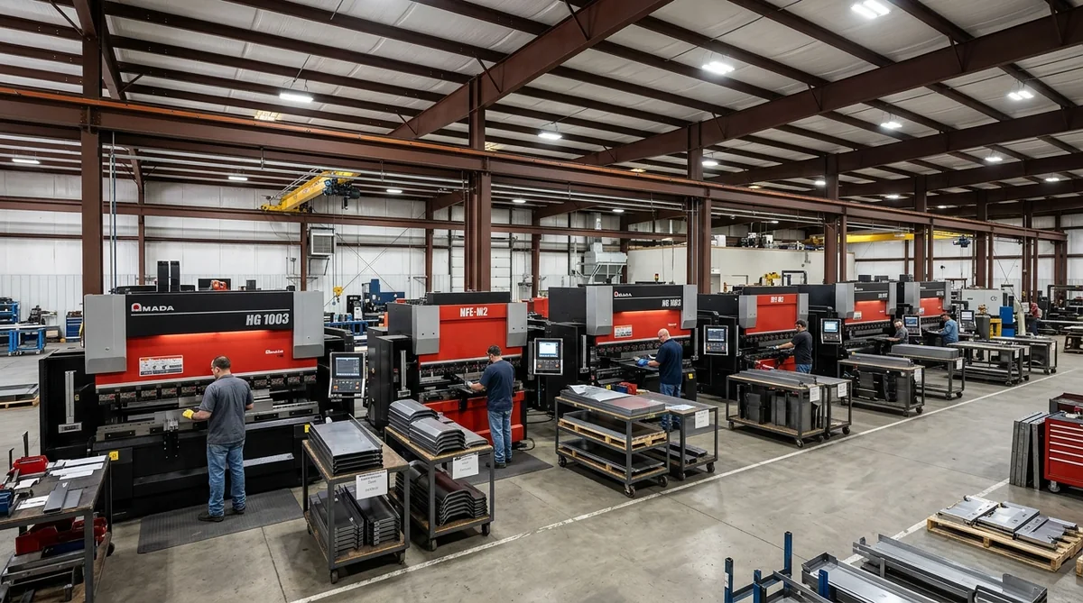
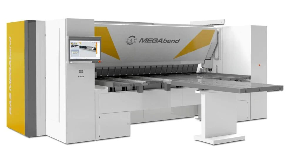
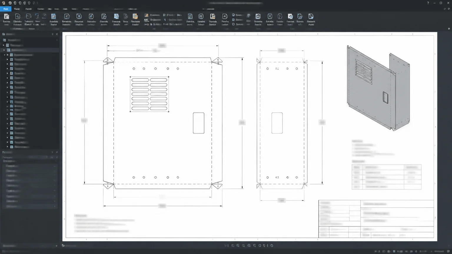
FabTek engineering unfolds customer models in SolidWorks and Inventor using bend deductions calibrated to FabTek’s own Amada press brakes and MEGAbend panel folder tooling, and keeps the flat patterns and bend programs by part number so repeat orders run without re-engineering. When a customer supplies flat patterns, engineering checks them against the formed model during DFM review before anything is cut.
Frequently asked questions
What is a K-factor in sheet metal?
The K-factor is the location of the neutral axis, the layer that neither stretches nor compresses in a bend, expressed as a fraction of material thickness measured from the inside of the bend. It is typically about 0.33 for tight bends, about 0.40 for most air-bent steel sheet, and up to 0.50 for large radii.
What is the formula for bend allowance?
Bend allowance equals pi divided by 180, times the bend angle in degrees, times the inside radius plus the K-factor times the material thickness. For a 90-degree bend in 14-gauge steel with a 0.075 inch radius and K of 0.40, the bend allowance is about 0.165 inch.
What is the difference between bend allowance and bend deduction?
Bend allowance is the length of the neutral axis through the bend, added to the flat legs. Bend deduction is the amount subtracted from the sum of the outside flange dimensions to get the flat length. Bend deduction equals twice the outside setback minus the bend allowance.
What K-factor should I use in SolidWorks?
A K-factor of about 0.40 to 0.44 is a common starting point for air-bent steel sheet with an inside radius near the material thickness. The final flat pattern should come from the fabricator's calibrated bend table for the actual material and tooling.